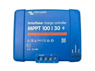
STEP 8: CABLE SIZING FOR SOLAR POWER SYSTEM

 Parameters Recap from our previous sizing steps

1. Daily Energy Consumption: 20.75 kWh
2. Total Peak Power: 3430 W
3. Days of Autonomy: 2 days
4. Solar Hour: 4 hours
5. Calculated Solar Array Value: 6.48 kW
6. Number of Solar Modules: 22 pieces of 300W modules
7. Battery Bank Size: Approximately 960.65 Ah at 48V (with 90% DOD)
"DOD" stands for (Depth of Discharge)
8. Inverter Sizing: 5KVA inverter is ideal for the system
9. Charge Controller Size: 170A (rounded up from 168.75A with a safety margin of 25%)
Number of Charge Controllers Needed: 2 (assuming 100A controllers are used)
10. System Cable Sizing?


AMPERCITY TABLE FOR COPPER CABLE

SN

AWG/kcmil

Approx. Area (mm²)

SWG Equivalent

Insulation Type (90°C)

Ampacity in Conduit or Raceway

Free Air Ampacity

1

14 AWG

2.08

16 SWG

THWN-2/THHN

25 Amps

30 Amps

2

12 AWG

3.31

14 SWG

THWN-2/THHN

30 Amps

41 Amps

3

10 AWG

5.26

12 SWG

THWN-2/THHN

40 Amps

55 Amps

4

8 AWG

8.37

10 SWG

THWN-2/THHN

55 Amps

70 Amps

5

6 AWG

13.3

8 SWG

THWN-2/THHN

75 Amps

95 Amps

6

4 AWG

21.15

6 SWG

THWN-2/THHN

95 Amps

125 Amps

7

3 AWG

26.67

5 SWG

THWN-2/THHN

115 Amps

145 Amps

8

2 AWG

33.62

4 SWG

THWN-2/THHN

130 Amps

170 Amps

9

1 AWG

42.41

3 SWG

THWN-2/THHN

150 Amps

195 Amps

10

1/0 AWG

53.49

2 SWG

THWN-2/THHN

170 Amps

230 Amps

11

2/0 AWG

67.43

1 SWG

THWN-2/THHN

195 Amps

265 Amps

12

3/0 AWG

85.03

0 SWG

THWN-2/THHN

225 Amps

310 Amps

13

4/0 AWG

107.2

00 SWG

THWN-2/THHN

260 Amps

360 Amps

14

250 kcmil

126.7

-

THWN-2/THHN

290 Amps

420 Amps

15

300 kcmil

152

-

THWN-2/THHN

320 Amps

480 Amps

16

350 kcmil

177.3

-

THWN-2/THHN

350 Amps

530 Amps

17

400 kcmil

202.7

-

THWN-2/THHN

380 Amps

575 Amps

18

500 kcmil

253.3

-

THWN-2/THHN

430 Amps

665 Amps

19

600 kcmil

304

-

THWN-2/THHN

475 Amps

750 Amps

20

750 kcmil

380

-

THWN-2/THHN

535 Amps

855 Amps

21

1000 kcmil

506.7

-

THWN-2/THHN

615 Amps

1035 Amps


CABLE SIZING
To determine the appropriate cable size for your solar power system, we'll refer to the ampacity requirements for each connection: from the solar arrays to the charge controllers, from the battery bank to the charge controllers, and from the battery bank to the inverter. Let's break down the requirements based on the details you provided:

Connection from Solar Arrays to Charge Controllers
- Total Ampacity Requirement:170A (from two 100A controllers)
- Use case: Connection likely to be split between the two controllers; each carrying about 85A.

Given each charge controller handles around 85A, we should select a cable size that can handle at least this current under the conditions the cables will be used (either in conduit or in free air).

 Connection from Battery Bank to Inverter
- Inverter Size: 5KVA, and assuming a nominal 48V system, the maximum current the inverter might draw:
 
  Max Current = Power (VA)/Voltage (V) = 5000/48 = 104 Amp

This calculation assumes full capacity usage of the inverter under normal conditions.

Selection of Cable Size Based on Ampacity Table
- We need to consider whether cables will be in a conduit or in free air, as this affects the allowable ampacity. The table provides different values for these scenarios. Since solar installations often use conduits for protection, we will consider the "Ampacity in Conduit or Raceway" values.

From Ampacity Table
1. For 85A per controller (solar arrays to charge controllers)**:
   - 6 AWG /16mm/8 SWG: 95 Amps in open air, which is good in open air.
   - 4 AWG /20mm/6 SWG: 95 Amps in conduit, which is suitable.
   
2. For 104A (battery to inverter):
   - 3 AWG /25mm/5 SWG: 115 Amps in conduit, which is suitable and provides a safe margin.

 Cable Size Selection
- Solar Arrays to Charge Controllers: Use 4 AWG cable, sufficient for 95 Amps which provides a margin above the 85A requirement.
- Battery to Inverter: Use 3 AWG cable, which can handle up to 115 Amps, providing adequate capacity for the 104A maximum expected current.


This selection assumes the cables will be installed in a conduit, as is typical for enhanced protection in solar installations. If the cables are in free air, the capacities will increase, potentially allowing for the use of smaller gauge wires. However, for safety and compliance with local regulations (including factors like voltage drop over distance, which hasn't been calculated here), it's advisable to confirm this selection with a qualified electrician or refer to the latest applicable electrical codes.


SUMMARY OF PARAMETERS AFTER EIGHT STEPS OF SIZING

PARAMETER

VALUE

Daily Energy Consumption

20.75 kWh

Total Peak Power

3430 W

Days of Autonomy

2 days

Solar Hour

4 hours

Calculated Solar Array Value

6.48 kW

Number of Solar Modules

22 pieces of 300W modules

Battery Bank Size

Approximately 960.65 Ah at 48V (with 90% DOD)

Inverter Sizing

5KVA inverter is ideal for the system

Charge Controller Size

170A (rounded up from 168.75A with a safety margin of 25%)

Number of Charge Controllers

2 (assuming 100A controllers are used)

Cable Size from Arrays to Controllers

4 AWG, 20 mm², 6 SWG

Cable Size from Battery to Inverter

3 AWG, 25 mm², 5 SWG


Comments

Popular posts from this blog

Solar Power system sizing

Discover the solar irradiance and solar hour of your location for proper sizing of solar power system

Why Mixing Battery Types in Your Solar Power System is a Bad Idea